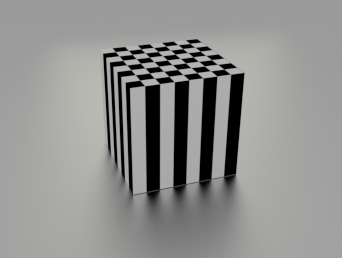
What i want to do is to project a texture to an object with a cubic, generated projection. Just like when you use the old Blender Materials: Coordinates - Generated, Projection - Cube. This should then look like this (Blender Internal Render):
But the only result i could achieve with Cycles so far was this one:
which is, of course, not exactly the same. So here comes my question: is this not implemented yet, or is there some mathematical magic to use with the vector / mapping / whatever node to get the image mapping like above?
Same problem here. I have a feeling, that this is either not implemented or not meant to be used that way. I will try to work around with UV Unwrapping
You would probably need to use the object mapping accessed by the texture coordinate node in this case, as the automatic coordinates like box, sphere, and cylinder are not supported yet (otherwise you need an actual UVmap).
To help with the mapping, you should add a mapping node as well to allow the translation, rotation, and scaling of the coordinates.
I stumbled on the same problem; I can see the new 2.61 release has the input options improved and tried adding a mapping node but can’t get my head around it. All I manage is to move and rotate a flat mapping, not getting the cube result. Is there eny way to do this?
Note: I’m by no means good with Cycles or the Node editor. There may be better ways to do this but this is how I solved the problem. Sorry about the size of the images. Use the horizontal scroll bar on the bottom to see what’s going on in the right panel.
I split my screen and used the Rendered view in Cycles on the right. It seems the default image projection is on the Z face. From there I added two more textures to the cube. Labeled the first one Default, in hindsight maybe should have labeled it Z, but the other two are X and Y.
Took me a moment to realize I had to hit “Use Nodes” (I think that’s what the button said). Went to the Node Editor in the list from the button on the bottom left, circled in red. By default it will already have the Diffuse and Material Nodes. Hit Shift + A to add a Textured Coordinate.
Same thing, added the Mapping Node. This Node is how you’ll rotate the image.
Added in the Image Texture Node.
Linked the Nodes and for the sake of ease made the World lighting white. I hit the Open button on the Image Texture Node and grabbed a grass image just for the example. If you notice, as in the other images, the sides are all stretched out. I had this same problem, thought I’d look for an answer, but looked like no one had found one yet.
I went back to 3D and out of the Node Editor. Once the Nodes are attached, you can change the settings in the panel on the right like the old Blender Internal Render. I copied the material and applied it to the other two materials. Makes it easier than adding in the nodes for all 3. I grabbed the two X faces and assigned them to Material X.
I’m hoping this will help explain what is happening. The default placing is facing on the Z axis. You essentially want to take that face and show it on the X axis. Now for the confusing part, you have to rotate it on the Y axis to get it to show on the X face. If it’s easier to remember, just do opposites.
In the settings, it’s always X,Y,Z in that order. Remember graphing in Algebra? Who knew that stuff would be useful? Under Rotation, rotate the Y setting 90 degrees. (Input 90.)
You may have to hit Tab to exit edit mode to see the changes real time.
Repeat for the other two faces. Enter Edit Mode by hitting Tab, grab the Y faces, Assign Material Y to them and input 90 in the X Rotation setting.
Perhaps in the future they may have some preset or node that will make that easier, but for now, this at least works.
Akexis: You can probably do the same thing in just one material.
Just use three different mapping nodes, three image nodes, and a geometry node along with color mix nodes to put it all together. (use the normal output in the geometry node along with the separate RGB node to make stencils)
since you use an external image you do have to unwrap it i guess. you could unwrap and use cube projection. better way is to use the uvmap modifier but that is some more work.

 Use the horizontal scroll bar on the bottom to see what’s going on in the right panel.